Information about Quality Level B (QLB) by a utility locator for a utility locating.
The Quality Level B (QLB) locating and markings are a important part of the utility surveying process, providing accurate and reliable data regarding the location and characteristics of underground utilities.
Quality Level B surveys are commonly used in subsurface utility locating jobs. QLB utility locating involves the use of electromagnetic technology to identify, locate and protect underground utilities.
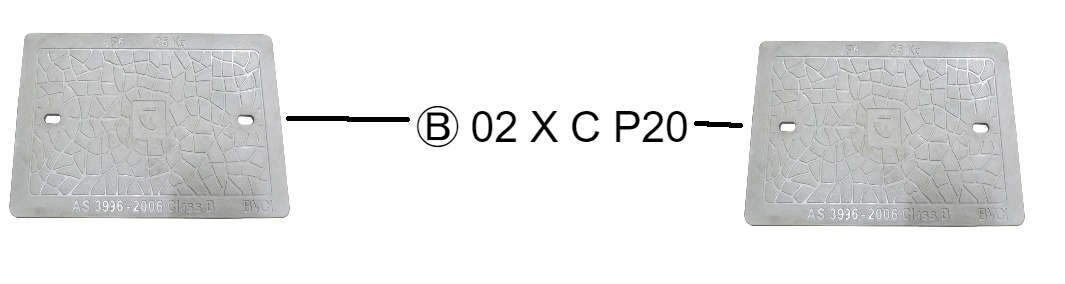
In this post, we’ll explain the basics of what checks a utility locator needs to make in order to depict a target signals location as a Quality Level B (QLB) locate mark. Sometimes, depicted on-site spray marks as the letter B with a circle around it. Ⓑ
What is a Quality Level B (QLB) Marking?
A QLB marking is a type of survey that is used to gather detailed information about the location and characteristics of underground utilities.
This type of survey is commonly used in construction and engineering projects where it is important to know the exact location and depth of utilities, such as water lines, gas lines, and electrical conduits.
The goal of a QLB survey is to provide accurate and reliable data that can be used to minimize the risk of damage to underground utilities during construction and excavation.
 Quality Level B = Significant Risk Reduction
QLB locates provides relative subsurface feature locations in three dimensions.
The minimum requirement for a QL-B locate is to have a relative spatial position of a utility, this can be achieved via an electromagnetic frequency locating device.
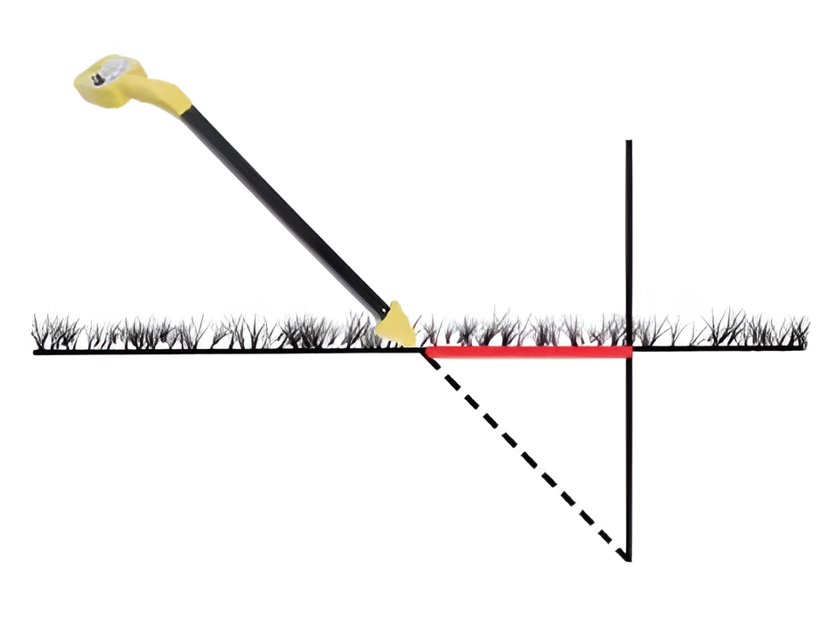
 All signal checks (mentioned on this page) Visual check (pit to pit, pipe to pipe, utility to utility) Maximum tolerance levels of +/- 300mm Horizontally Maximum tolerance levels of +/- 500mm Vertically.
An electronic location provided by a DBYD "Certified Locator" to QL-B standard, and would have a maximum horizontal tolerance of plus or minus 300mm and a maximum vertical tolerance of plus or minus 500mm.
In order to make a QLB locate marking, a utility locator must make seven checks for accuracy.
What Checks Does a Utility Locator Need for a QLB Locate Mark?
There are seven checks for a electromagnetic utility locator QLB mark.
Here is a step by step checklist to see if your on the right target utility line and your signal is not distorted.
Once you have these checks in place your marking is a confirmed as a Quality Level B (QLB) marking.
1
 Visual Confirmation
When marking a QLB locate, a utility locator must follow any signal to a visual access point where they can confirm they are on the right line.
Pit to Pit, Cable to Cable, Pipe to Pipe or Meter to Meter, Pole to Pole, Substation to substation (etc.) or any variations. You must locate the signal to a visual confirmation, for a QLB locate.

2
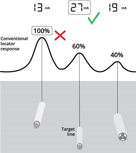
㎃ MilliAmps (mA)
Utility locators must also check the milliamps of the signal to confirm they are on the target line. The signal should be gradually losing millamps the further away it is from its signal connection. If the utility signal drops suddenly or halves, this could indicate a conductive signal bleeding.
3
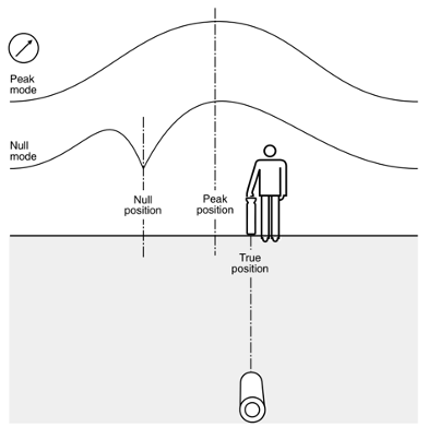
ᨒ Peak vs. Null
The peak signal and null signal should match. If they don’t match, there could be interference with the target signal from a more conductive material, other environmental signals, pipe or cable.
When the peak and null signals do not match, you can use the 2/3rd rule to find target location.
2/3rd Rule: Mark the peak and null signals, then measure the distance between peak and null signal marks, two thirds (2/3) of the signal measured, on the opposite side of the peak signal is your true position of the target signal. If the peak and null singals are not within tolerances of (+/-) 300mm/30cm, it cannot be marked as a QLB locate.
4
⩇:⩇⩇ Digital Depth
Utility locators must lift the EM locator a certain measured distance from the ground and check to see if the digital depth reading matches the increase.

5
△ Triangulation
〇 To check the signal is round on the △ lower sides of the target, Utility locators should hold the receiver on a 45-degree angle and pull it to either side of the peak until the receiver reading is balanced. Both sides should be equal, if the field shape is round.
6
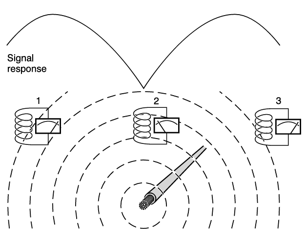
︵ Signal Peak
At its simplest it is apparent that an aerial produces the strongest response when it is as close as possible to the buried conductor and in correct alignment with it, i.e. at right-angles to it and directly above it.
To check if the peak signal is round, The utility locator operator should wave the receiver an equal distance on either side of the center of the peak signal (locator always point horizontally) and the equal and opposite distance should have matching readings. Also known as, A smooth peak signal.

Detailed Theory: This shows the difference in response as the receiver traverses over the line through positions 1, 2 and 3. The response at position 2 is greatest not only because of the proximity of the aerial to the line, but also because of the full alignment of the aerial core with the field direction, so that it is linked with a higher proportion of the field.
Because the response is related to the orientation of the aerial core relative to field direction it is also related to line direction. So a horizontal aerial gives two pieces of information - line position and its direction. This makes a horizontal antenna preferable for general sweeping, locating and tracing work.
7
︶ Null Signal
To check if the null signal is round, The utility locator operator should raise the receiver straight up vertically in null mode. The reading should still indicate a null signal in the same position, if the signal is round.
Any deviations means something is distorting the signal. It may be a nearby utility, site interference, a conductive material or object, or even a unknown. Its always a good idea to note and do your best to address it for accurate data, reporting and positive results.
This ‘null’ signal is easier to detect than a ‘maximum’ signal position, so a vertical aerial would seem to pinpoint a line with greater precision.
Null Signals are more prone to interference and therefore less accurate than a peak locate.
However, it gives no indication of line direction, so is much less suited to normal location and tracing duties. Its still useful for cross checking accuracy when pinpointing with a horizontal aerial instrument.
Detailed Theory: The vertical orientation of the aerial produces a completely different effect, because the flux linking, the core falls sharply to zero as it reaches the same position directly above the conductor.
Flux linkage is the linking of the magnetic field with the conductors of a coil when the magnetic field passes through the loops of the coil, expressed as a value.
 Conclusion of QLB Locates.
 These checks are important to ensure significantly increase in accuracy and greatly minimize the risk of damage to underground utilities during construction and excavation.
We hope this post has been helpful in providing you with an overview of Quality Level B (QLB) locate standard, and signal checks, for professional utility locating in the field.
If you have any further questions or need help with your project, We encourage you to always consult with a professional utility locator before any excavation.